

Family project • Launched November 2022 • Testing in progress
AIS — Automated build-plate swapping for a 3D printer farm
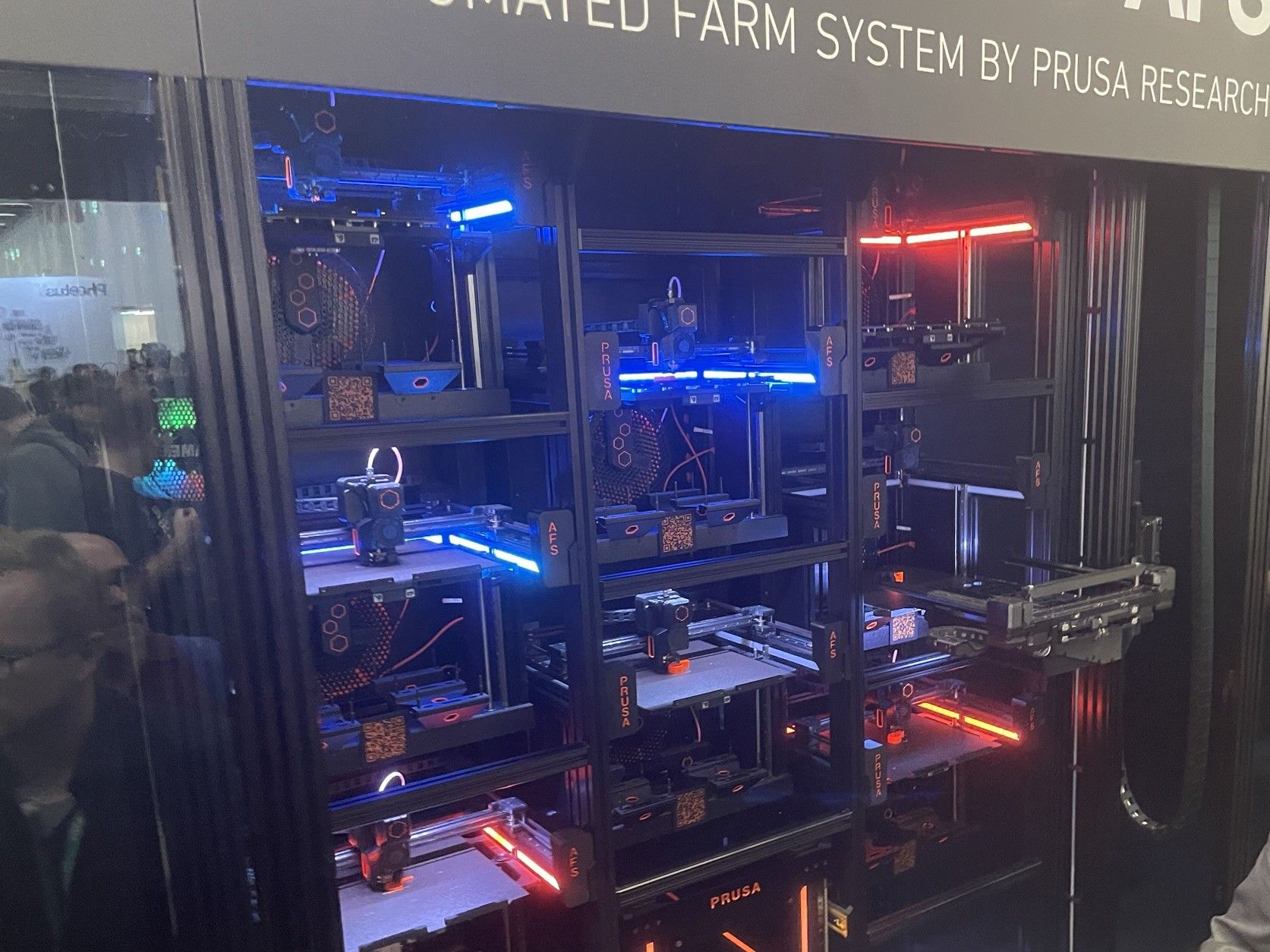
AIS is our internal automation project, inspired by the Prusa Pro Automated Farm System (AFS): a robotic setup designed to swap full build plates for empty ones so that a group of printers can run for longer without human intervention.
Project origin
The AIS project took shape in November 2022, following our visit to Formnext in Frankfurt — the major international trade fair for additive manufacturing. There we discovered the Prusa Pro AFS (Automated Farm System) concept, a robotic system capable of automatically swapping build plates across a printer farm. The idea immediately seemed transposable to our own setup.
Why this project matters to us
At home we run around ten 3D printers. Internal tracking revealed a striking fact: despite the time spent manually restarting prints, actual printing accounts for only about 20 % of available time. The rest is idle time — full plate, printer waiting. AIS aims to fix that and move toward 24/7 production.
- Goal: keep printers productive overnight and during unsupervised periods
- Constraint: robust mechanics + safe handling of warm build plates
- Approach: modular structure + robotic arm + sensors + reliable power distribution
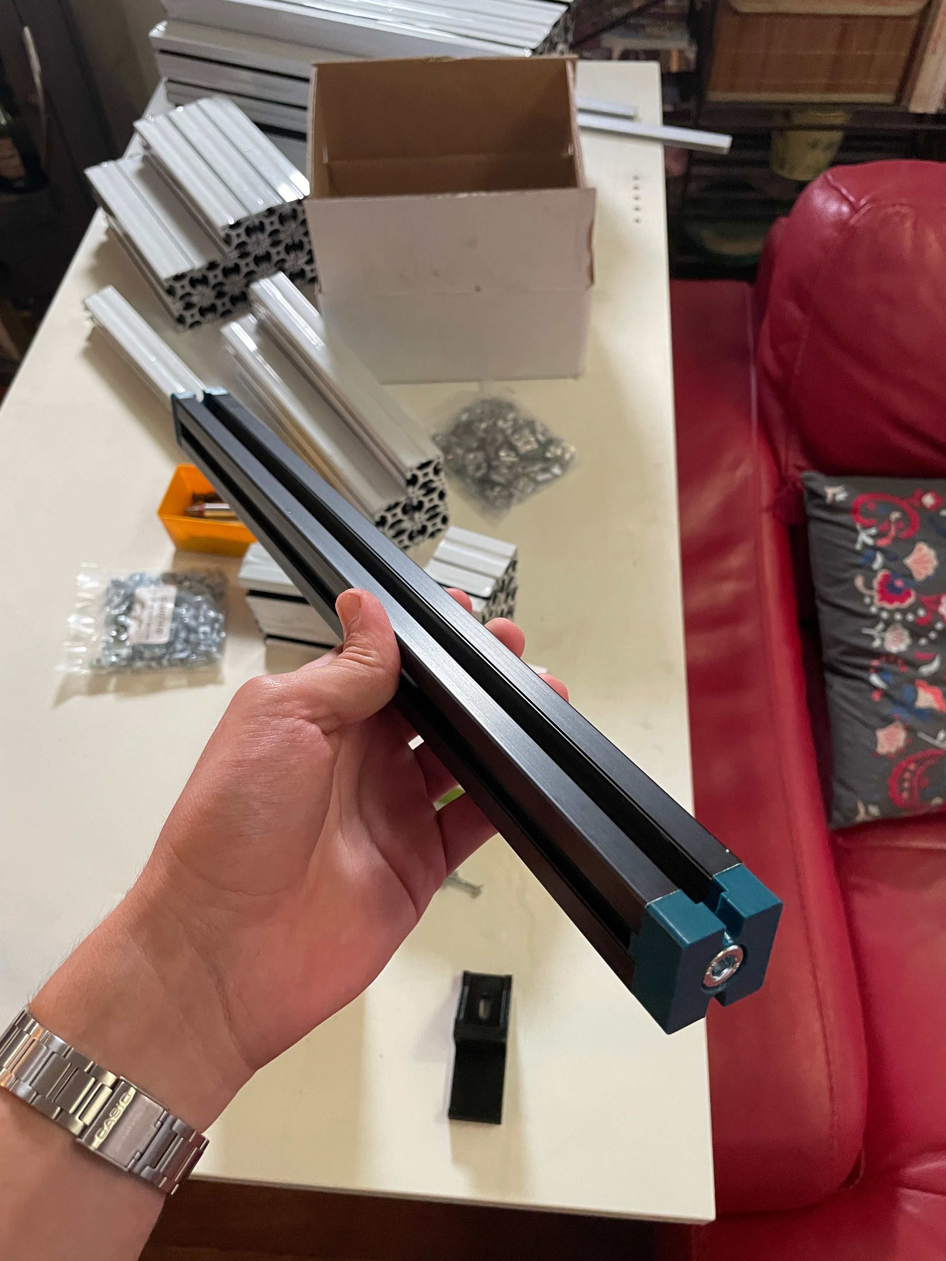
Frame structure — aluminium extrusion assembled to form the rigid modular support for the system
Team and responsibilities
Frédéric Berlocher
- Full mechanical design in Fusion 360
- Parts sourcing and supplier coordination
- Organising 3D printing of functional parts
- Mechanical assembly of the frame and arm
Maxime Berlocher
- Power distribution architecture and sizing
- Axis control strategy (drivers, homing, limit switches)
- Wiring and electrical schematic documentation
- Arduino programming of motion cycles
- First motor tests and gripper test on bench
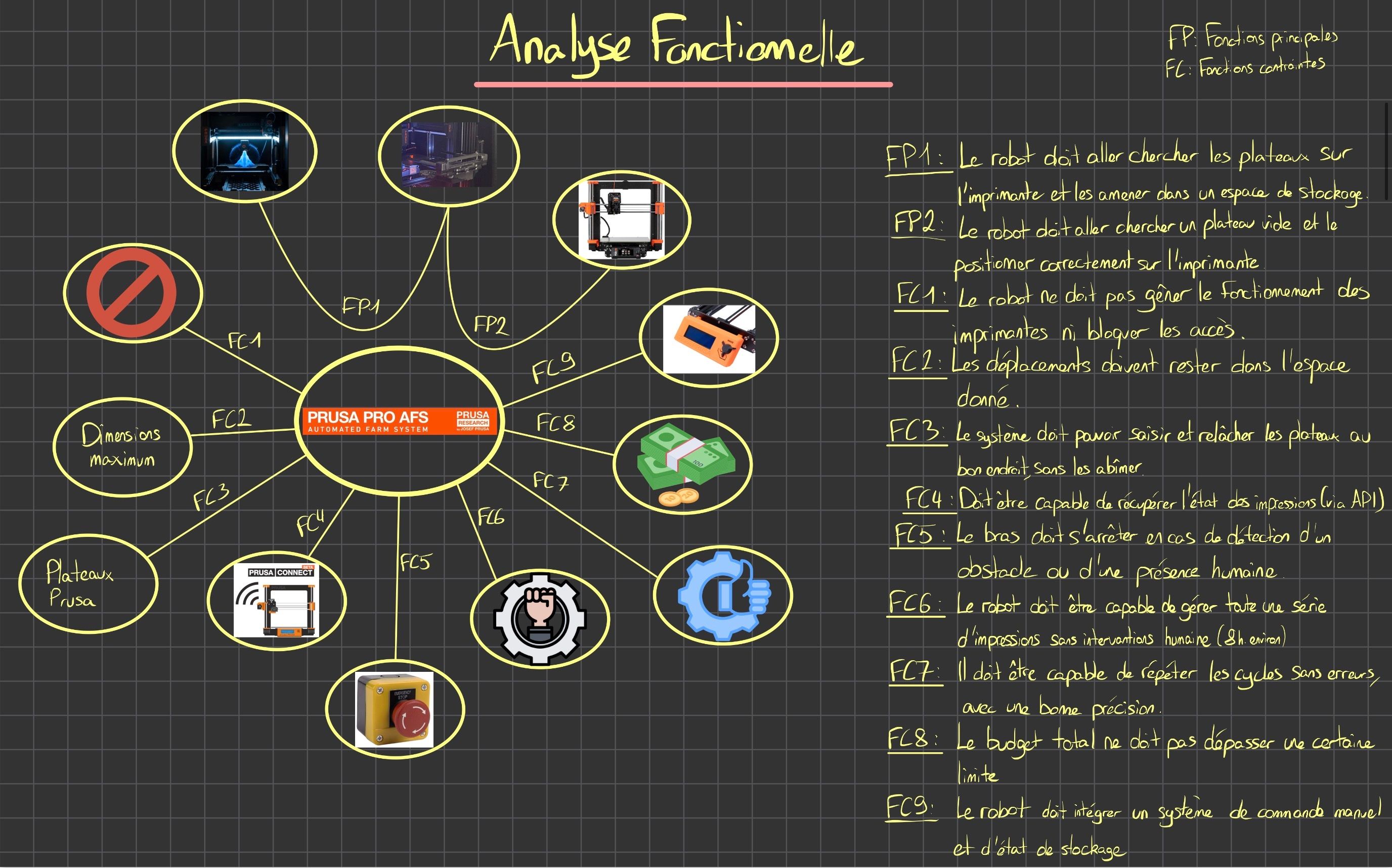
Functional analysis document — click to enlarge
Functional analysis
Before any development work, I carried out a structured functional analysis of the system, identifying the main functions (FP) the robot must fulfil and the constraint functions (FC) it must respect.
Main functions
FP1: The robot must pick up full plates from the printer and bring them to a storage area.
FP2: The robot must retrieve an empty plate and position it correctly on the printer.
Constraint functions:
- FC1: Must not interfere with printer operation or block access
- FC2: All movements stay within the defined envelope
- FC3: Grips and releases plates without damaging them
- FC4: Retrieves printer status via API
- FC5: Emergency stop on obstacle or human presence detection
- FC6: Manages a series of prints without human intervention
- FC7: Repeats cycles without errors at adequate precision
- FC8: Stays within budget
- FC9: Integrates a manual control interface and storage status display
Solution research
I conducted a comparative research phase to select the electronics and control strategy. For each sub-system I evaluated several options based on performance, cost, and ease of integration.
Motor drivers
BIGTREETECH TMC2209 (UART, microstepping, thermal protection)
Microcontroller
Arduino UNO — prototype; Teensy 4.1 compared for final version
Motors
NEMA 17 (4-wire) — frame size [TO FILL: 34 mm or 48 mm retained]
Encoder
AS5048A optical encoder studied — [TO FILL: model and resolution retained]
Power supply
24 V DC — Mean Well LRS-350-24 / NES-350-24 compared — [TO FILL: model used in prototype]
L298N (discarded)
Classic H-bridge — excessive heat losses, no native microstepping
Why we chose the TMC2209
Compared to the L298N, the TMC2209 offers microstepping (up to 1/256), UART communication for dynamic configuration, automatic load detection (StallGuard) usable for sensorless homing, and built-in thermal protection — decisive advantages for a system running unattended.
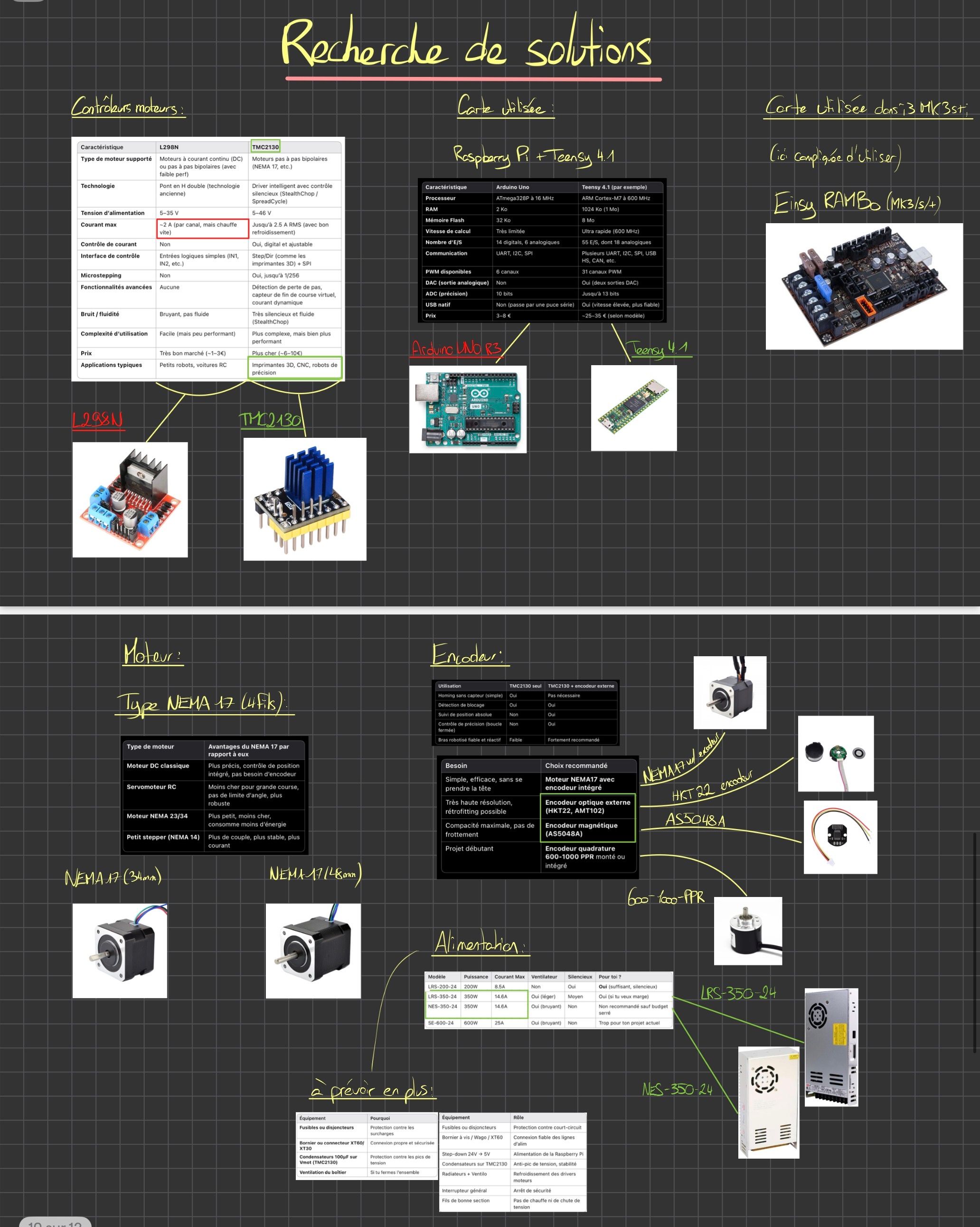
Solution research document — click to see the full two-panel document
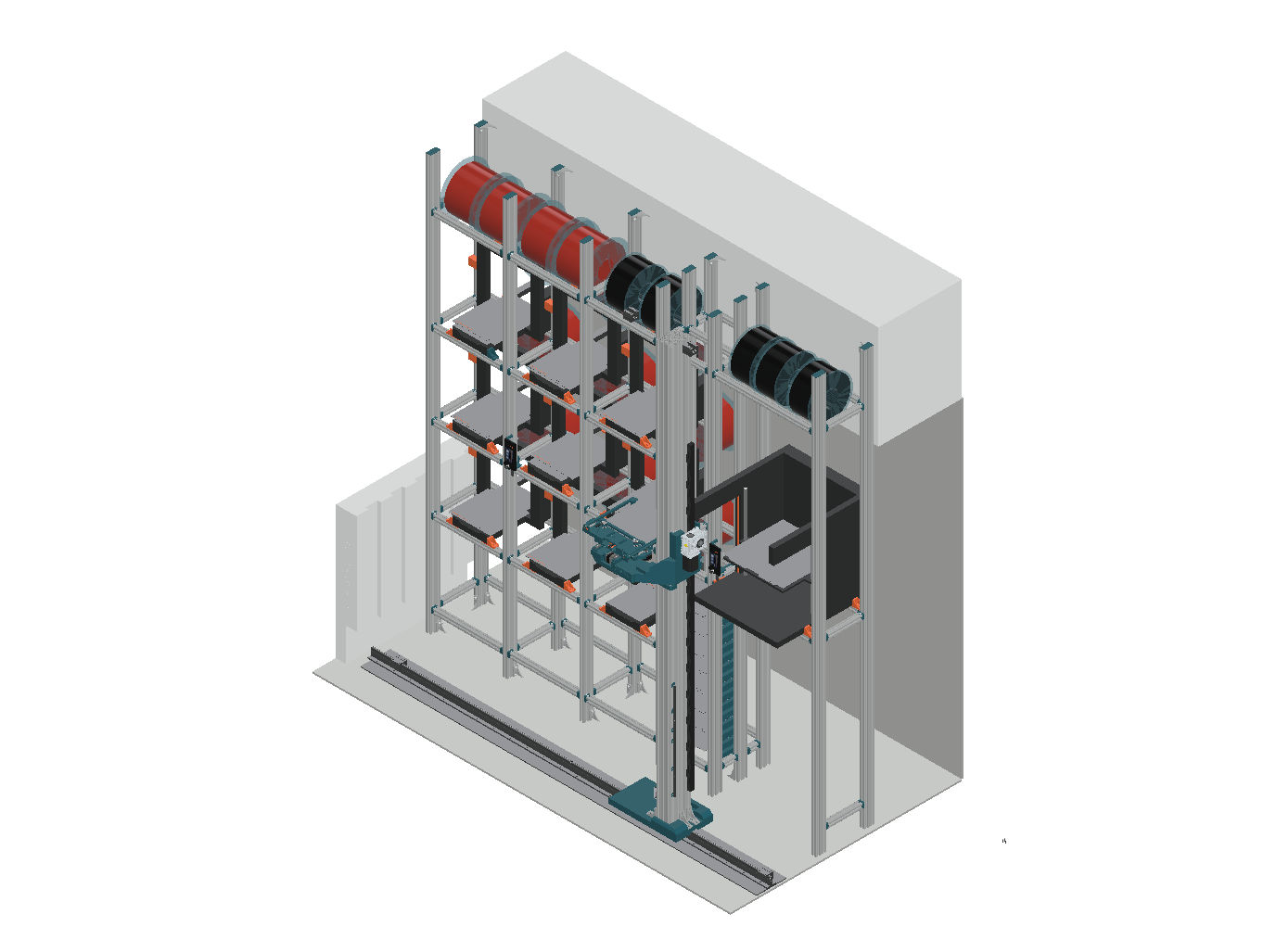
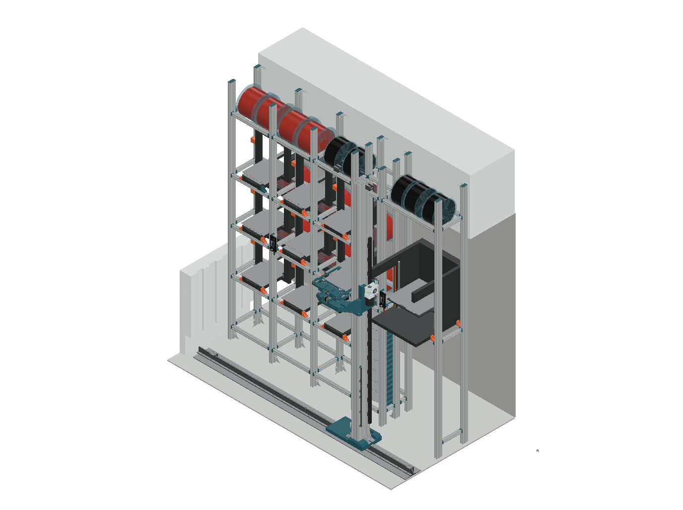
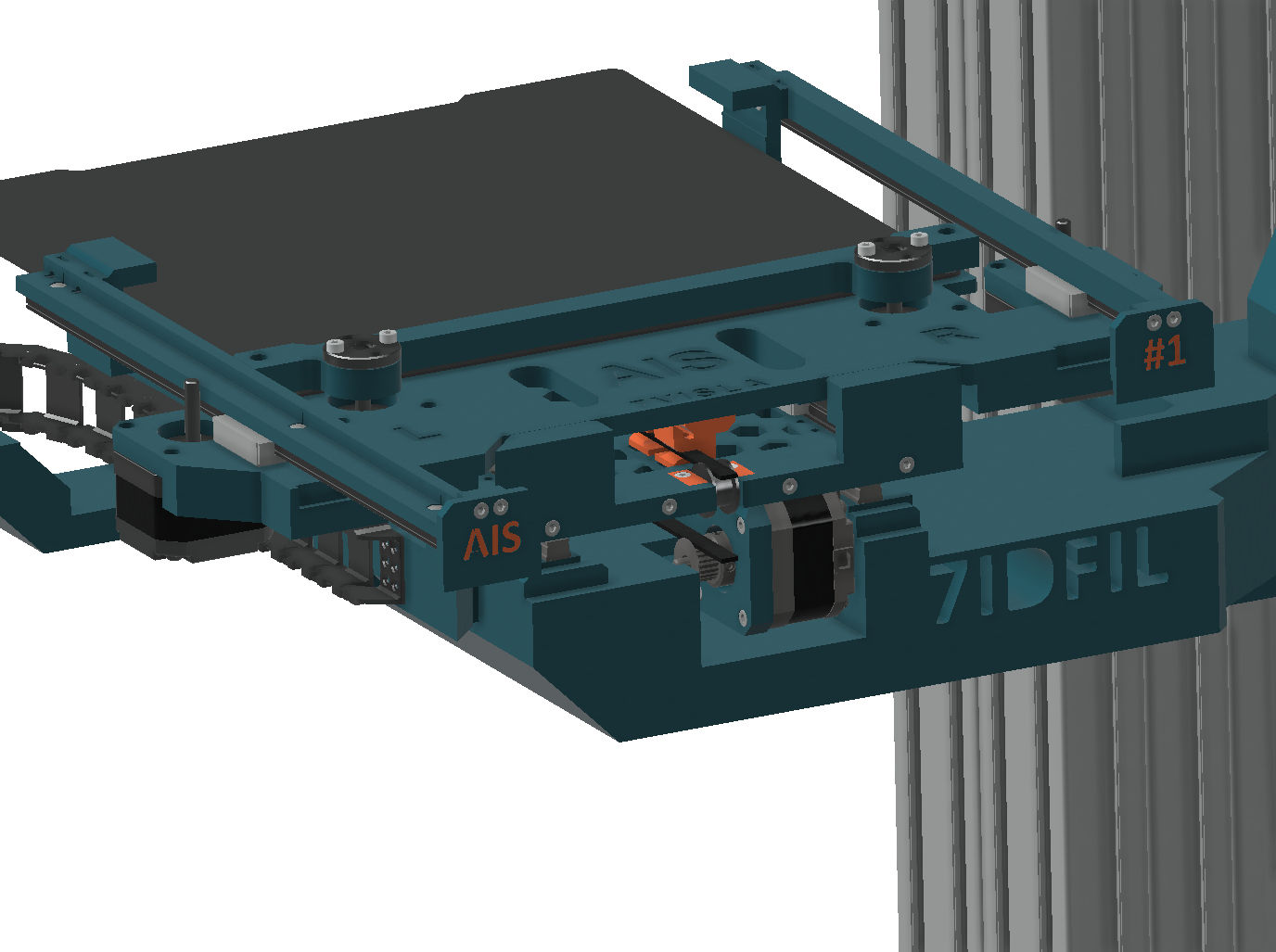
Fusion 360 model — printer rack and plate-handling arm concept
Mechanical architecture
The first phase laid the foundations: a rigid frame to support the printers and an arm concept capable of handling plates in a repeatable way. The structure combines metal extrusions for rigidity and 3D-printed connectors/brackets for rapid iteration.
Frame structure
Aluminium extrusion + custom-printed connectors
Arm parts
Mainly 3D-printed in PETG
Iteration
CAD → print → test cycles, fast redesign
Assembly
Metal + PETG-printed interface parts
Electronics and control — my contribution
This is the core of my work on this project. I designed the power distribution architecture, established the connections between all system components, produced the wiring schematics, and programmed the first axis control cycles on Arduino.
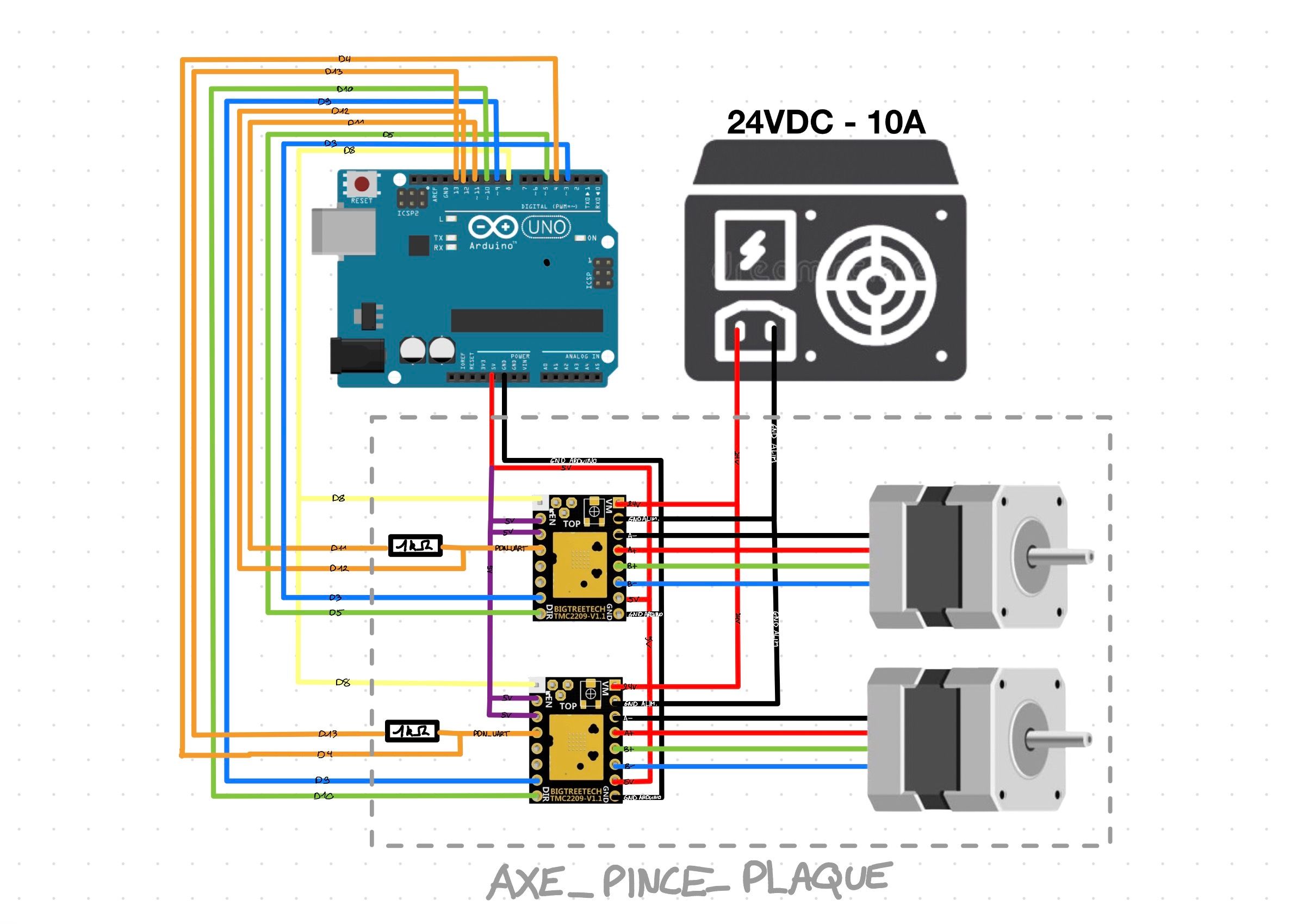
Wiring schematic — AXE_PINCE_PLAQUE sub-system (click to enlarge)
AXE_PINCE_PLAQUE sub-system architecture
This schematic represents the first sub-system I fully wired and tested: the axis controlling the plate-gripping mechanism. It uses the following components, all selected after the solution research phase:
- Arduino UNO — main microcontroller for the prototype
- 24 VDC / 10 A power supply — power bus for actuators
- 2× BIGTREETECH TMC2209-V1.1 — stepper motor drivers (UART mode)
- 2 NEMA 17 stepper motors — axis actuators
- 2 limit switch sensors — end-stops for axis homing
Connection detail
The Arduino digital pins (range D2–D13) are connected to the TMC2209 drivers for direction (DIR), step (STEP), and enable (EN) signals. Limit switches are wired to dedicated digital inputs. The 24 V supply is distributed directly to the drivers (motors); the Arduino is powered separately via USB during development.
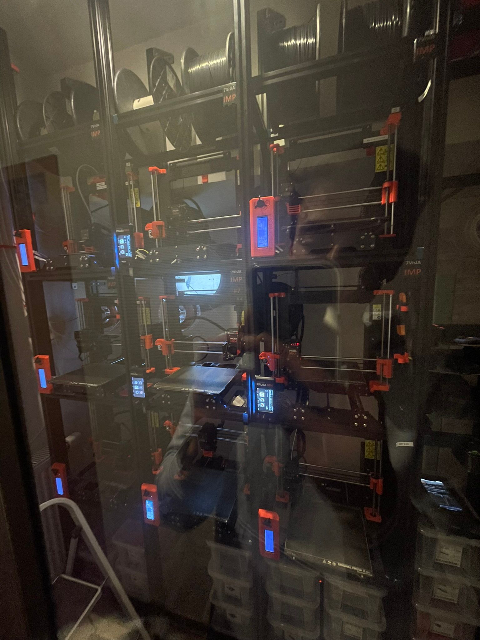
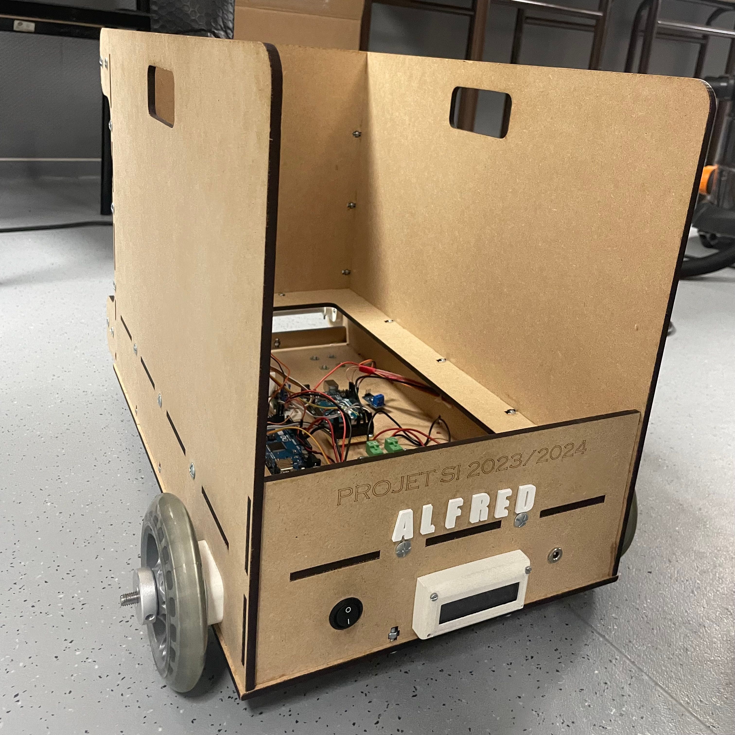
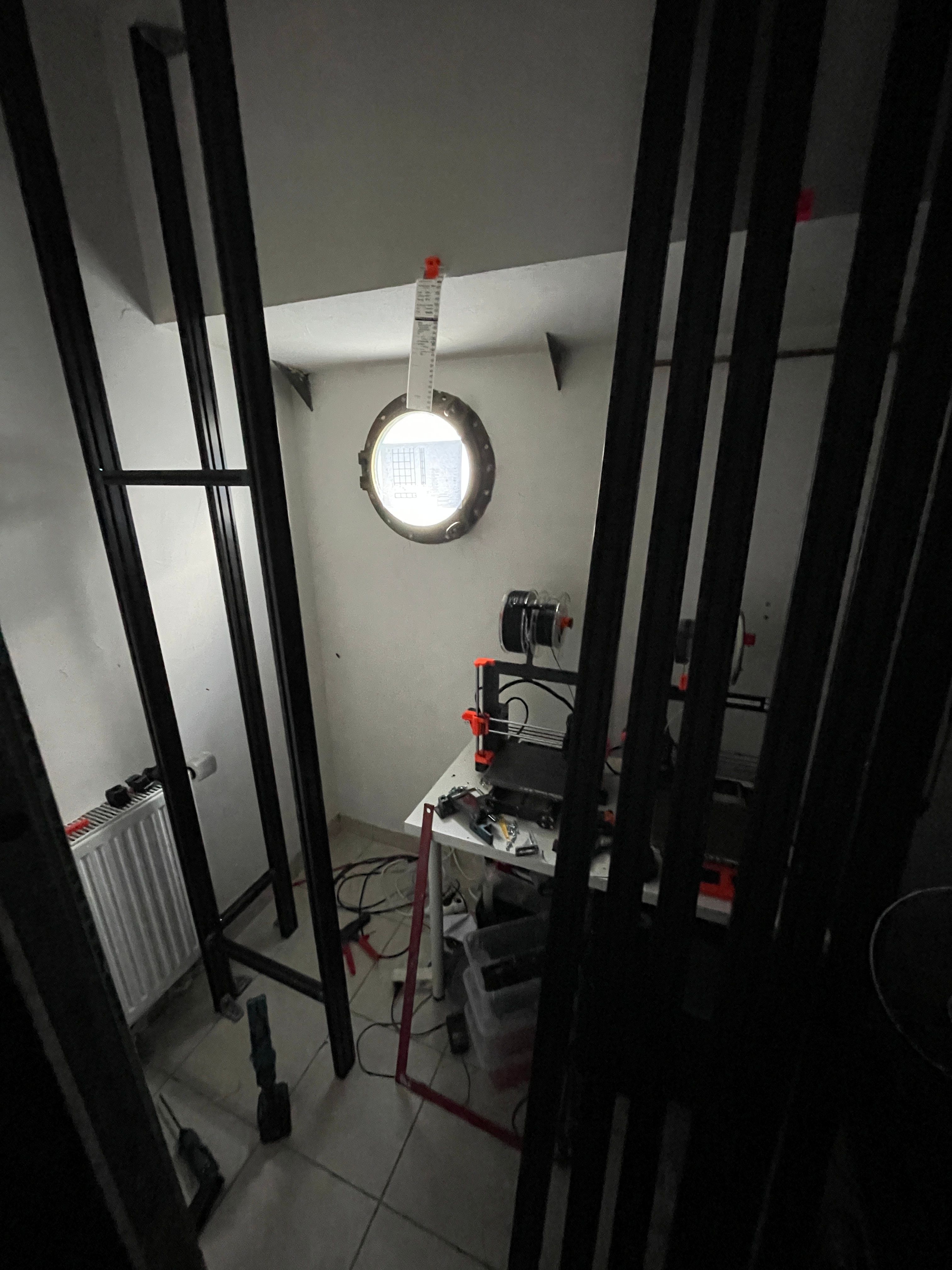
Physical frame — assembled chassis; next step: arm fabrication and electronics integration
Axis control strategy
Beyond wiring, I defined the motion control strategy to ensure reliable and safe operation across unsupervised cycles:
- Automatic homing: each axis re-calibrates to its limit switch on startup
- TMC2209 microstepping: fine movement resolution, reduced vibration
- UART mode: dynamic motor current configuration and temperature monitoring from Arduino
- Software emergency stop: immediate cut-off if a sensor detects an anomaly (FC5)
- Schematic documentation: annotated wiring with wire and connector labelling
Electronics priorities
Long-term reliability and maintainability: clearly identified failure modes, clean wiring with identification markers, ability to service a sub-system without dismantling the whole assembly.
Tests carried out
Concrete tests have already been run: bench motor drive, Arduino motion-cycle programming, and a first test of the plate-gripping mechanism.
Plate gripper test — prototype (click to enlarge)
Plate gripper test
The video shows the first functional test of the build-plate gripping mechanism, carried out off the final structure to validate the gripping concept before full mechanical integration.
Test objective
[TO FILL: describe the precise objective — gripping validation, force, positioning?]
Results
[TO FILL: observed results and conclusions from IMG_4190 test]
Video compatibility note
This video is in .mov format (native Apple). It plays correctly in Safari. For playback in Chrome or Firefox, an .mp4 (H.264) version is required — to be created from the source file and hosted on ImageKit.
Electronics test bench
To validate motor control before integration into the frame, I set up a table test bench. This setup allowed me to verify connections, develop the Arduino program, and observe actual motor behaviour (steps, direction, current).
- Arduino UNO connected to laptop for development and upload
- TMC2209 drivers on breadboard, wired per the AXE_PINCE_PLAQUE schematic
- Two to three NEMA 17 motors connected (one with lead screw)
- Multimeter to check voltages and wiring consistency
- Arduino program development: step cycles, limit-switch homing, direction control
Testing approach
Goal → Setup → Observations → Corrections → Iteration. Every anomaly found on the bench is documented and fixed before mechanical integration. This approach greatly reduces the risk of having to disassemble the full system later.
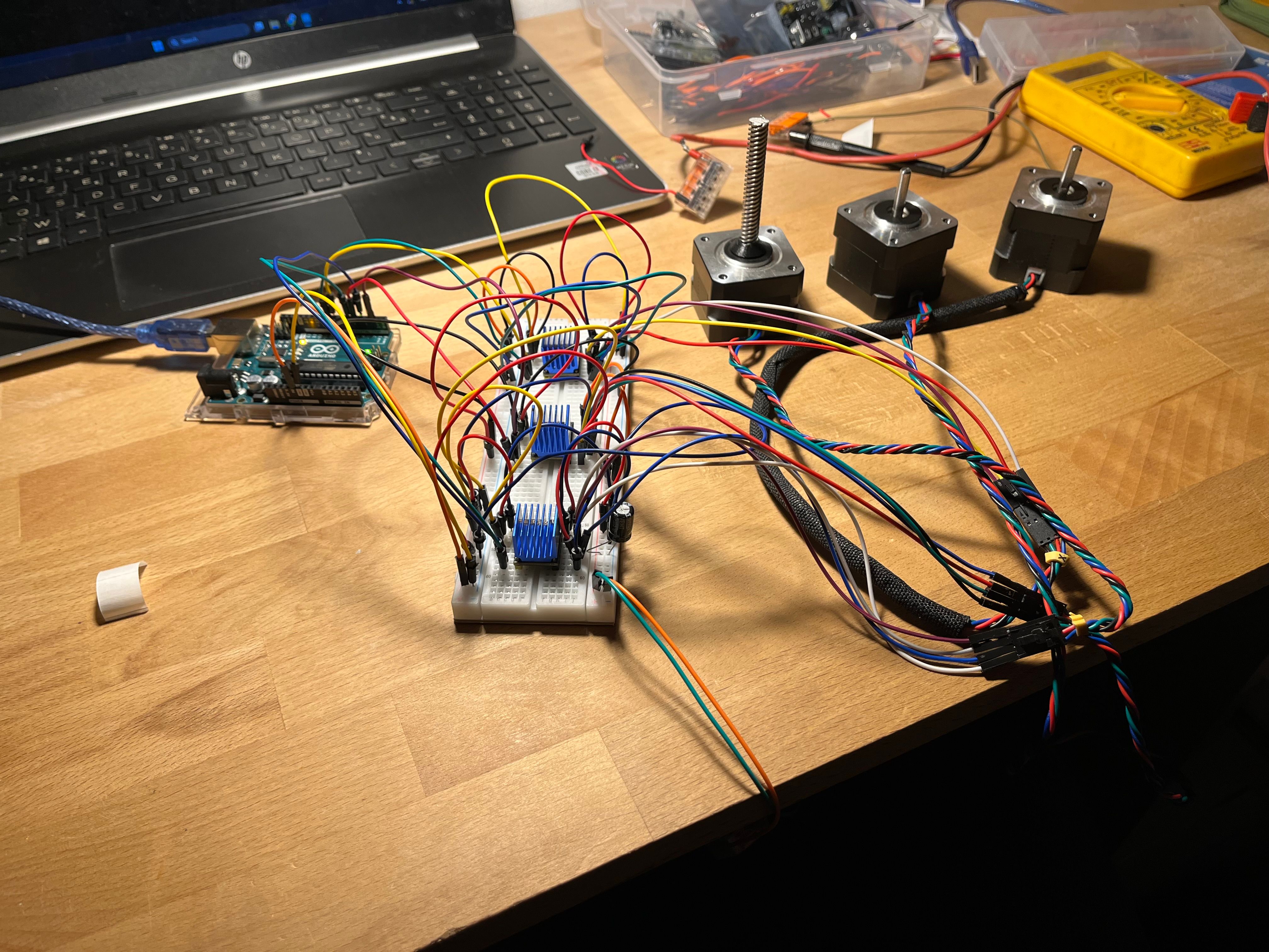
Test bench — Arduino UNO, TMC2209 drivers, NEMA 17 motors, multimeter visible in the background
Progress and next steps
Phase 1 — Inspiration and feasibility ✓
Observed the Prusa Pro AFS concept at Formnext (Nov. 2022), adapted it to our farm's constraints and workflow. Functional analysis completed (FP/FC) and feasibility confirmed.
Phase 2 — Mechanical design and sourcing ✓
Fusion 360 modelling of the rack and arm, selection of aluminium extrusions, preliminary chassis assembly. Functional PETG parts printed and tested.
Phase 3 — Electronics specifications and first tests ✓ (partial)
Comparative component research, AXE_PINCE_PLAQUE wiring schematic produced, test bench assembled. First motor drive tests and gripper test completed.
Phase 4 — Full build and integration (in progress)
Printing remaining PETG arm parts, installing motors and sensors in the final structure, full wiring, and system validation: repeatability tests, multi-axis homing, and complete plate-swap cycle.
Gallery
Additional project visuals (structure, workshop, assembly).
Key takeaways
- A printer farm's productivity is often limited by handling time, not print speed — automating plate swapping changes the equation entirely.
- A structured functional analysis (FP/FC) before touching any mechanics or electronics prevents costly architectural mistakes later.
- Choosing TMC2209 drivers over classic H-bridges illustrates the value of picking components with built-in features (StallGuard, UART, microstepping) rather than reimplementing them yourself.
- Bench testing before mechanical integration — even simple setups — reveals wiring and logic issues that would be very costly to fix once the system is assembled.
- Automation is only robust if failure modes are identified at design time (emergency stop, reliable homing, wiring documentation).